Splitting Light with Precision
Every interferometer, spectrometer, and laser system that measures something meaningful relies on a beamsplitter to divide a single beam into two. The quality of that division, whether by intensity ratio, polarization state, or wavelength band, directly governs the signal-to-noise floor of the entire measurement. A 50/50 split that is actually 48/52 introduces fringe contrast loss. A polarizing beamsplitter with imperfect extinction leaks orthogonally polarized light into the wrong arm, corrupting phase data.
At Eata Ray, we fabricate and coat beamsplitters exclusively for research environments where these imperfections cannot be tolerated. From plate beamsplitters for high-power laser chains to cube beamsplitters for interferometric metrology, our processing pipeline delivers components whose splitting ratios, wavefront fidelity, and polarization performance match the optical prescription.
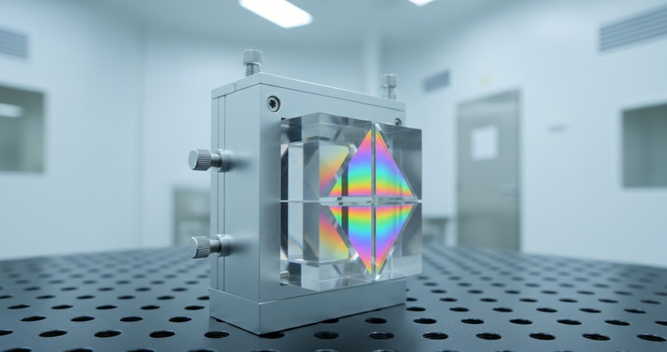 Figure 1. A precision beamsplitter cube mounted in a cleanroom fixture, with the internal hypotenuse coating visible as an interference color pattern.
Architectures and Manufacturing Approaches
Beamsplitters come in two fundamental physical forms, each with distinct manufacturing pathways and performance trade-offs. Our facility maintains expertise in both, allowing us to recommend and fabricate the most suitable architecture for your optical system.
Plate Beamsplitters
A plate beamsplitter consists of a flat optical substrate with a partially reflective coating on the front surface and an anti-reflection coating on the rear. The transmitted beam undergoes a slight lateral shift due to refraction through the plate thickness, an effect that must be accounted for in precision alignment.
- Front-surface dielectric or hybrid coatings provide the splitting function, with ratios such as 50/50, 30/70, or 90/10 achievable across UV, visible, and infrared bands.
- Rear-surface AR coatings minimize ghost reflections that would otherwise create secondary interference patterns in the downstream optical path.
- Wedge angles between front and rear surfaces can be introduced to steer ghost images out of the system field of view, a common requirement in imaging interferometers.
- Because there is no cement layer, plate beamsplitters tolerate higher power densities and broader temperature excursions, making them the preferred choice for laser resonators and industrial measurement systems.
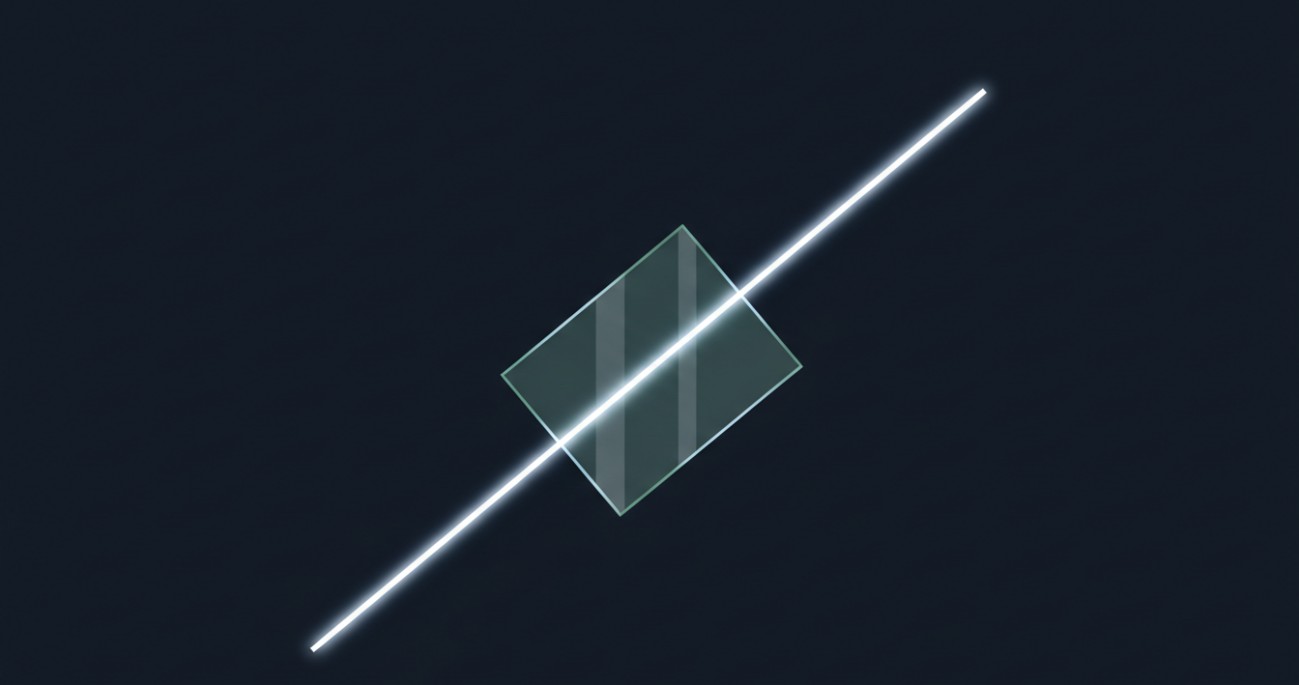 Figure 2. A plate beamsplitter dividing an incident beam into transmitted and reflected paths at a 45-degree angle of incidence.
Cube Beamsplitters
Cube beamsplitters are assembled from two right-angle prisms, with the splitting coating deposited on the hypotenuse of one prism before optical cementing or contact bonding. The transmitted beam exits collinear with the incident axis, eliminating the lateral displacement inherent to plate designs.
- The internal coating is protected from environmental contamination and physical contact, offering superior durability for field-deployed instruments and educational laboratories.
- All four external faces receive AR coatings to maximize throughput and suppress parasitic reflections that would degrade image contrast in imaging applications.
- Angular tolerances of the prism hypotenuse are held to arcminute or arcsecond levels, ensuring that the reflected and transmitted beams maintain precise orthogonality.
Polarizing versus Non-Polarizing Designs
The distinction between polarizing and non-polarizing beamsplitters lies in how they treat the s and p polarization components of incident light. Each type relies on a fundamentally different coating architecture.
- Polarizing beamsplitter cubes employ multilayer dielectric stacks on the hypotenuse, designed so that p-polarized light transmits with greater than 95 percent efficiency while s-polarized light reflects with extinction ratios exceeding 1000:1. These are essential for fluorescence microscopy, polarimetry, and laser cavity output coupling.
- Non-polarizing beamsplitters, whether plate or cube, use hybrid metal-dielectric coatings to maintain nearly equal splitting ratios for both s and p states, keeping polarization-dependent loss below 6 percent. They are the standard for imaging applications where polarization must be preserved, such as holography and white-light interferometry.
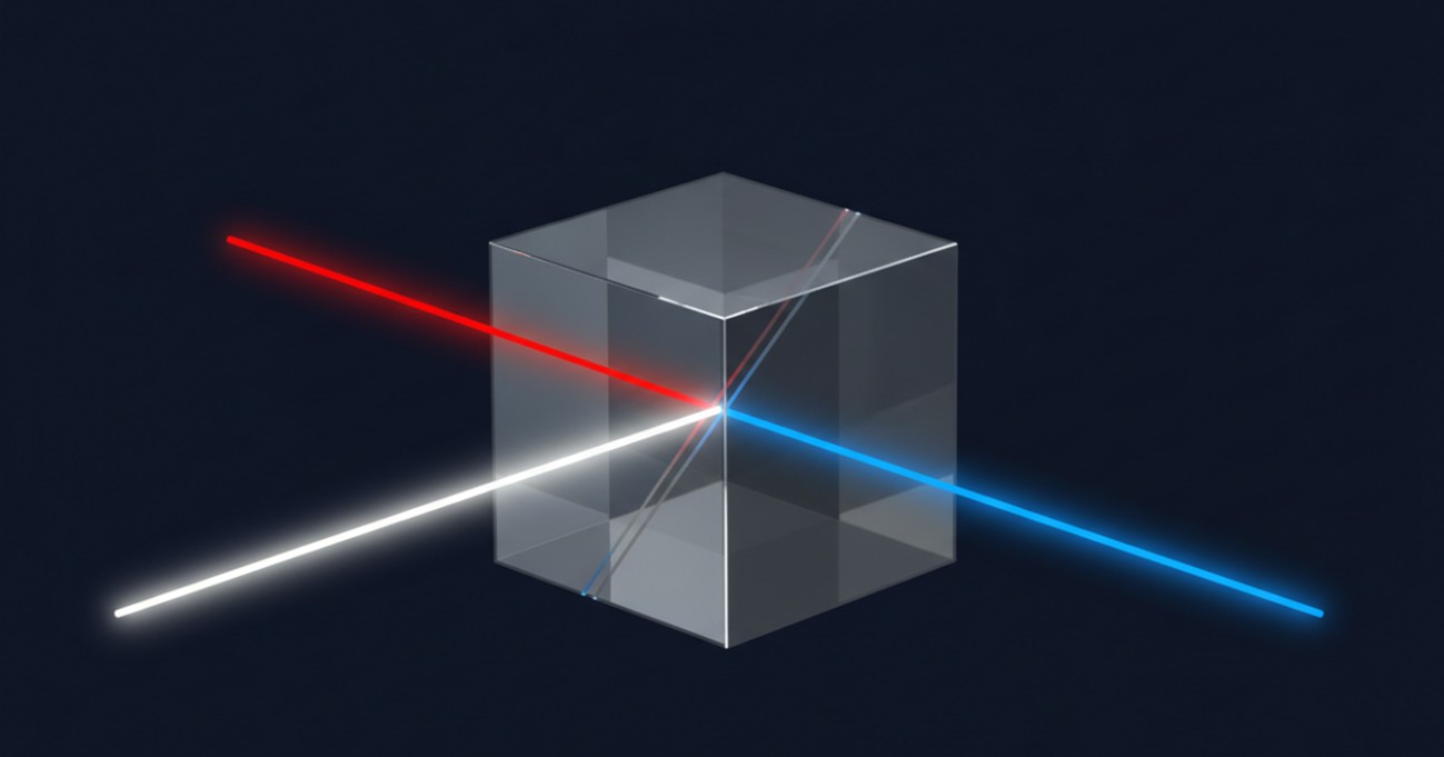 Figure 3. A polarizing beamsplitter cube separating an incident beam into orthogonal polarization states via the internal dielectric coating interface.
Thin-Film Coating Deposition
The coating is where the beamsplitter becomes functional. Our in-house deposition capability spans multiple technologies, each matched to the spectral band, power level, and environmental stability requirements of the research application.
- Electron beam evaporation with ion-assisted deposition produces dense, environmentally stable oxide coatings suitable for visible and near-infrared beamsplitters operating under moderate power.
- Ion beam sputtering yields ultra-low-loss, high-damage-threshold films with sub-Angstrom surface roughness, the preferred route for high-power laser beamsplitters and ultraviolet systems.
- Hybrid metal-dielectric coatings combine the spectrally flat response of thin metal layers with the low absorption of dielectric overcoats, achieving the polarization-insensitive performance required for non-polarizing designs.
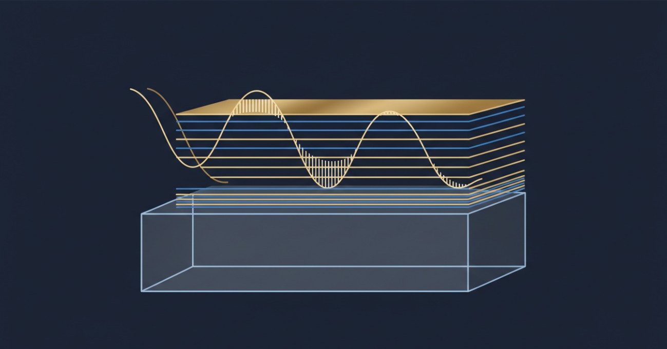 Figure 4. Cross-sectional visualization of an alternating high-low index multilayer coating stack engineered for precise reflectivity and transmission control.
Achievable Specifications
Research beamsplitters must satisfy exacting tolerances across dimensional, angular, and spectral dimensions. The table below summarizes the parameter ranges our standard processing workflows routinely hold.
| Parameter |
Range / Options |
Notes |
| Clear Aperture |
3 mm to 100 mm |
Custom dimensions reviewed case by case |
| Dimensional Tolerance |
±0.1 mm to ±0.05 mm |
Tighter on micro-optic assemblies |
| Angle Tolerance |
±3 arcmin to ±3 arcsec |
Autocollimator-verified during assembly |
| Surface Flatness |
λ/4 to λ/10 @ 632.8 nm |
λ/20 available on critical faces |
| Surface Quality |
40-20 to 10-5 scratch-dig |
Per MIL-PRF-13830B |
| Split Ratio |
50/50, 30/70, 40/60, 90/10, custom |
±5% tolerance, tighter on request |
| Extinction Ratio (PBS) |
>100:1 to >1000:1 |
Dielectric multilayer on hypotenuse |
| Polarization Sensitivity (NPBS) |
<6% difference between Ts and Tp |
Hybrid metal-dielectric coating |
| Coating Wavelength |
190 nm to 15 µm |
AR, BBAR, laser-line, and broadband designs |
| Substrate Materials |
N-BK7, fused silica, UV fused silica, ZnSe, CaF2, sapphire |
Matched to spectral and thermal requirements |
Research Applications We Support
Beamsplitters fabricated at Eata Ray have been integrated into instruments spanning the full spectrum of optical research. Representative application areas include:
- Laser interferometry: Non-polarizing plate and cube beamsplitters with sub-lambda/10 wavefront error for Michelson, Mach-Zehnder, and Fizeau interferometers used in surface metrology and gravitational-wave reference systems.
- Fluorescence and confocal microscopy: Polarizing beamsplitter cubes with high extinction ratios for separating excitation and emission paths in epi-illumination systems, maximizing signal collection efficiency.
- High-power laser systems: Water-cooled plate beamsplitters with IBS dielectric coatings and damage thresholds exceeding 20 J/cm2 for beam sampling, power monitoring, and harmonic separation in fusion research.
- Spectroscopy and spectral imaging: Dichroic and polychroic beamsplitters that separate excitation bands from detection bands in Raman spectrometers, flow cytometers, and multispectral imaging platforms.
- Quantum optics and entangled photon sources: Polarizing beamsplitters with ultra-low loss for Bell-state analysis, Hong-Ou-Mandel interference, and quantum key distribution receiver modules.
- Optical coherence tomography: Broadband 50/50 fiber-coupled beamsplitters with flat spectral response across 100-nm bandwidths for high-resolution biomedical and industrial OCT systems.
Verification and Spectral Characterization
A beamsplitter cannot be trusted until its splitting ratio, spectral response, and polarization behavior have been quantified against calibrated references. Our metrology suite provides that confidence.
Spectrophotometers measure transmission and reflection from the ultraviolet through the long-wave infrared, generating spectral curves that confirm coating performance at every wavelength in the design band.
Laser-based bench testing at specific wavelengths validates split ratios, extinction ratios, and absolute throughput using power meters traceable to national standards.
Interferometric flatness testing ensures that coated surfaces do not introduce wavefront distortion that would degrade fringe contrast in an interferometer or broaden the focal spot in an imaging system.
For polarizing beamsplitters, complete Mueller matrix characterization is available on request, quantifying not only extinction ratio but also diattenuation, retardance, and depolarization across the full aperture.
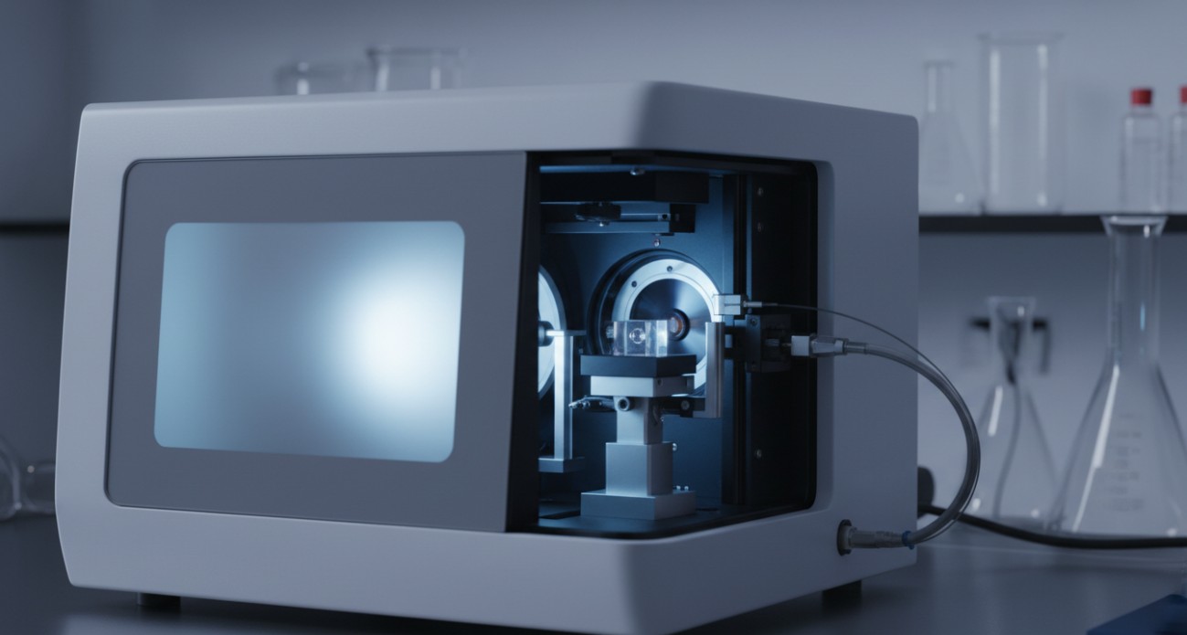 Figure 5. A spectrophotometer measuring the spectral transmission and reflection characteristics of a coated beamsplitter in our metrology lab.
Engagement and Collaboration
Research beamsplitters are almost always custom entities, defined by a unique combination of wavelength, split ratio, polarization requirement, and mechanical envelope. Our engagement model is structured to navigate that complexity alongside you.
- Requirement Discussion: Send us your optical prescription, including wavelength range, split ratio, polarization sensitivity, power level, and mechanical constraints. If you are unsure which architecture, plate or cube, best suits your system, we advise based on alignment sensitivity and environmental tolerance.
- Design and Coating Specification: Our engineers select the substrate material, define the coating architecture, and model the spectral performance. We share the predicted transmission and reflection curves for your review before deposition begins.
- Prototype Fabrication: A single prototype beamsplitter is typically the most prudent first step. We fabricate, coat, and characterize the component so you can validate its performance in your optical system under real operating conditions.
- Characterization and Reporting: Each finished beamsplitter ships with spectral scan data, split ratio verification at specified wavelengths, and surface quality inspection results. Raw data files are provided alongside summary reports.
- Iterative Refinement: If the prototype reveals a need for adjustment, whether to the split ratio, spectral band edge, or polarization extinction, we modify the coating design and produce a revised iteration.
Discuss Your Beamsplitter Requirements
Whether your research calls for a delicate 50/50 cube for a white-light interferometer, a high-damage-threshold plate for a laser sampling application, or a dichroic beamsplitter with a steep spectral edge for a fluorescence microscope, our team is ready to translate your specification into a verified optical component.
Reach out with your beamsplitter challenge and receive a technical feasibility assessment at no initial charge.


